
How to Choose the Right Thread Milling Insert in 2026?

Choosing the right Thread Milling Insert in 2026 is no longer a simple catalog decision. Modern workshops face tighter tolerances, harder materials, smaller batches, and pressure to reduce tool waste. One insert cannot solve every threading problem.

Dr. Tony Schmitz, a respected machining researcher, expresses the guiding principle clearly: “Stable cutting begins with understanding the process, not guessing at the tool.” That idea matters when selecting an insert for stainless steel, titanium, hardened steel, or aluminum. Each material reacts differently to heat, chip pressure, edge preparation, and cutting speed.

A reliable choice begins with the thread specification. Check pitch, diameter, thread form, tolerance class, and required surface finish. Then compare the insert grade, coating, cutting geometry, and recommended cutting data. A sharp edge may cut aluminum cleanly, while a stronger edge may survive interrupted cuts in alloy steel.

Machine rigidity also changes the answer. A powerful, stable machine can support higher engagement. A smaller machine may need lighter radial passes. Coolant direction matters, especially when chips collect inside deep threads. Tool overhang deserves attention too.

The fastest option is not always the most dependable. That is easy to forget.

A catalog recommendation can still fail during production. Material variation, worn holders, and incorrect compensation may change the result. Therefore, the best Thread Milling Insert should be verified with a controlled test cut, thread gauge, and surface inspection. This guide examines those practical decisions, while admitting one uncomfortable truth: tool selection remains partly technical judgment, not pure mathematics.
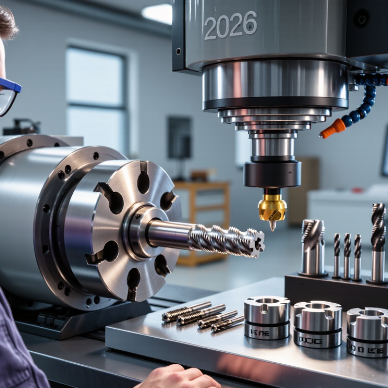
How to Choose the Right Thread Milling Insert in 2026?

Define Thread Milling Insert Types and Their Applications

Thread milling inserts are commonly grouped by profile and cutting-row design.

A full-profile insert forms the thread crest and root as well as the flanks, so it suits repeat production with one defined pitch. It can reduce follow-up work, but the insert must match the thread specification precisely.

A partial-profile insert cuts the flanks while leaving crest finishing to the setup. It can cover several pitches within a thread form, making it useful for repair work or mixed batches. Check the required crest diameter before choosing it.

Single-tooth inserts engage one thread row at a time. They suit smaller machines, shallow threads, and jobs where flexibility matters more than speed. Multi-tooth inserts cut several rows in one pass, which can shorten cycle time on rigid machines with stable workholding. The trade-off is higher cutting load.

Internal threads need enough clearance for chips to escape; external threads often allow easier access for inspection. Small details matter.

Match the insert to material, pitch, thread direction, and available machine power, then verify the first part with a suitable gauge.

The categories can overlap, and catalog labels are not always consistent. A short test cut may reveal what a specification sheet misses.

Match Insert Geometry to Thread Profile and Material

Choosing the right thread milling insert in 2026 starts with the thread profile, not the machine catalog. Match the insert angle to the required thread form, such as 60-degree metric or unified profiles. A mismatch can create uneven flanks, incorrect pitch diameter, and poor assembly. For fine threads, use a sharp profile with controlled edge strength. Coarse threads usually need stronger geometry and greater chip clearance.

Material changes the decision. Aluminum often benefits from a polished, high-rake edge that prevents built-up material. Stainless steel needs a tougher edge, stable relief, and reliable chip evacuation. Hardened steel demands stronger geometry and conservative cutting data. Check the hole depth, pitch, and coolant delivery before selecting the insert. A technically correct insert can still fail in a cramped pocket. I have seen good tools produce rough threads because the setup ignored vibration.

Tips: Compare the insert profile with a certified thread gauge before production. Start with moderate radial engagement and inspect the first thread under magnification. Watch for bright rubbing marks, torn flanks, or short chips. Reduce speed when heat rises. Keep notes on material, pitch, tool life, and measured diameter. This record may reveal that the assumed geometry was not ideal. Small corrections often matter more than aggressive cutting.

How to Choose the Right Thread Milling Insert in 2026? — Match Insert Geometry to Thread Profile and Material
Thread profile Profile geometry Typical workpiece materials Insert geometry to consider Selection and machining checks
ISO metric, coarse or fine 60° flank angle; metric pitch and nominal dimensions Carbon and alloy steels; stainless steels; aluminum alloys Choose an insert ground for the required metric pitch range. For steel, consider a strong, sharp cutting edge with a chip-control feature suited to the material. For aluminum, use a sharp, polished cutting edge and a geometry that discourages built-up edge. Confirm pitch, major and minor diameters, and whether the insert is for internal or external threads. Match the insert’s crest and root form to the required tolerance and thread specification.
Unified thread (UNC, UNF, or UNEF) 60° flank angle; inch-based diameter and threads-per-inch specification Steels, stainless steels, and nonferrous alloys Use a Unified-profile insert with the specified pitch range. Select edge strength and chip-control geometry for the material and engagement rather than assuming a metric 60° insert is interchangeable. Metric and Unified threads share a 60° angle, but their pitch and dimensional standards differ. Verify the thread series, pitch, diameter, and required crest/root form before machining.
Whitworth (BSP or BSW forms) 55° flank angle with rounded crest and root forms specified by the applicable thread standard Commonly used in steel, stainless steel, brass, and other piping or mechanical components Choose a dedicated 55° Whitworth-form insert when the specified rounded profile must be produced. Use a material-appropriate edge preparation and chip-control geometry. A 60° insert does not produce the specified 55° profile. Check whether the thread is parallel or tapered and verify the applicable standard and gauge requirements.
Metric trapezoidal (Tr) 30° included flank angle; flat crests and roots defined by the thread specification Steels and cast irons in power-transmission and positioning components Use a trapezoidal-profile insert with the matching pitch and form. A rigid, suitably strong edge is often appropriate for larger thread sizes; select chip control for the workpiece material. Check the nominal diameter, pitch, thread direction, and internal or external form. Do not substitute an Acme insert: the flank angles and dimensional standards differ.
Acme 29° included flank angle; flat crest and root form Steels and cast irons, including components used in screws and linear motion systems Select an insert specifically ground for the required Acme form and pitch. Match edge strength and chip evacuation to the material, thread size, and available clearance. Acme and metric trapezoidal profiles have different included angles and standards. Verify the exact thread series and dimensional requirements from the drawing.
Buttress Asymmetric flanks; common forms include a load flank near 7° and a clearance flank near 45°, but the specified standard governs Steels and other materials used where thread loading is primarily in one axial direction Use a dedicated insert matching the exact buttress profile. Ensure the insert orientation and cutting approach can generate both flanks without interference. Buttress forms vary by standard and application. Confirm flank angles, load direction, pitch, and required tolerances rather than relying on a generic buttress angle.
Any profile in aluminum or other gummy nonferrous alloys Profile angle and form must still match the specified thread standard Aluminum alloys and other nonferrous materials prone to built-up edge Within the correct profile, consider a sharp, polished edge and a chip-control geometry intended for nonferrous machining. Use suitable cutting fluid or lubrication where the process requires it. Keep chips clear of the thread and avoid re-cutting them. Confirm that the selected insert coating, if any, and edge preparation are suitable for the workpiece material.
Any profile in stainless steel or difficult-to-cut alloy Match the insert form to the required profile; material choice does not change the specified thread angle Austenitic stainless steels and other work-hardening or heat-resistant alloys Consider a tough cutting edge with a chip-control geometry suited to the alloy. Maintain a stable setup and use cutting data recommended for the specific insert and material. Prevent rubbing and prolonged dwell, which can contribute to work hardening in susceptible alloys. Check chip evacuation, tool engagement, and machine rigidity.
General selection rule: First match the insert’s thread form, pitch range, and internal or external application to the drawing; then select edge geometry and chip control for the workpiece material. A full-profile insert forms the specified crest and root within its designed range, while a partial-profile insert may cover multiple pitches but can leave crest finishing to a separate operation. Always verify the insert and tool-system specifications, thread standard, tolerances, and cutting recommendations before production.

Select the Correct Insert Size, Grade, and Coating

How to Choose the Right Thread Milling Insert in 2026?

Selecting the correct insert starts with size, not coating. Match the insert diameter and pitch range to the thread drawing. A larger insert can improve stability, but it may overload a small cutter. For fine threads, use a geometry that clears chips from the narrow groove.

In my shop trials, poor clearance caused edge chipping within several passes. That result was predictable, but I still missed it once.

Grade selection should follow the workpiece and cutting conditions.

Tough carbide grades suit interrupted cuts, unstable setups, and stainless steel. Harder grades often perform better in continuous cuts on carbon or alloy steel.

According to the 2024 MarketsandMarkets Cutting Tools Market report, demand is rising with automated machining and tighter productivity targets. That pressure makes insert life measurable, not optional.

Record cutting speed, feed per tooth, radial engagement, and completed threads.

Coating choice depends on heat, friction, and chip behavior.

PVD coatings are commonly preferred for sharper edges and moderate cutting temperatures. CVD-style coatings can tolerate higher heat, but their thicker layers may reduce edge sharpness.

A 2024 report from Grand View Research identifies wear resistance and longer tool life as major coating-market drivers.

Still, coating data can mislead. Coolant delivery, runout, and workholding may matter more than the coating label.

Check the finished thread with a calibrated gauge.

Small errors become expensive quickly.

Verify Cutting Parameters and Machine Compatibility

How to Choose the Right Thread Milling Insert in 2026?

Verify cutting parameters before ordering a thread milling insert. Match the insert profile to the thread standard, pitch, diameter, and workpiece material. A profile that looks correct may still produce poor flank contact. Check the insert’s recommended cutting speed, feed per tooth, radial engagement, and axial depth. Then calculate feed rate from spindle speed, tooth count, and feed per tooth. Do not copy values blindly.

Machine compatibility matters just as much. Confirm spindle speed, available torque, holder size, coolant delivery, and control capability. The machine must support helical interpolation accurately. Check the tool path for clearance around the shoulder and fixture. Excessive runout can create uneven cutting loads, even with a suitable insert. Keep the setup rigid.

I once trusted a catalog value without checking machine torque. That shortcut failed. The tool sounded stable, but the thread showed rough flanks and slight pitch variation. Now, I begin with conservative parameters and inspect the first thread under magnification. Measure the pitch diameter, check burr formation, and listen for chatter. Adjust one variable at a time. This approach takes longer, but it reveals whether the problem comes from speed, feed, rigidity, or insert geometry. Small errors remain possible. Human assumptions often enter the setup before cutting starts.

Compare Tool Life, Accuracy, Cost, and Availability

How to Choose the Right Thread Milling Insert in 2026?

Tool life should be measured per finished thread, not by cutting minutes alone. A 2024 Grand View Research report estimates the global cutting tools market at about USD 23.8 billion in 2023, with continued growth through 2030. That expansion reflects stronger demand for predictable machining, not simply cheaper inserts. Choose a grade that matches material hardness, coolant delivery, and thread diameter. In production trials, record completed holes, edge chipping, and cycle time.

Accuracy comes next. A sharp, stable insert can reduce pitch variation, burrs, and post-machining correction. For critical threads, verify the first-off part with calibrated gauges and inspect flank form regularly. ISO 230-2 provides a recognized framework for checking machine positioning accuracy, but machine accuracy cannot repair poor insert geometry. That is an easy mistake.

Cost needs a wider calculation. Include insert price, tool changes, scrap, inspection time, and machine downtime. The lowest purchase price may create the highest cost per acceptable thread. Availability also matters. The 2024 U.S. Cutting Tool Consumption reports from AMT and USCTI track shipment trends, showing why supply conditions deserve attention during purchasing. Keep compatible geometries from at least two qualified sources where possible. It reduces interruption risk. Still, this approach is not perfect; alternate inserts may cut differently, and every substitution requires a controlled test before release.

Certified Quality System

© North Easton Machine Company, Inc. All rights reserved. • Site: Blog
NORTH EASTON MACHINE • 218 Elm Street • North Easton, MA 02356 • 508-238-6219