What Is CNC Machining and How Does It Work?

Cnc Machining has transformed how manufacturers produce accurate parts from metal, plastic, and composite materials. It uses computer-controlled movements to guide cutting tools along programmed paths. Unlike manual machining, the process can repeat complex operations with remarkable consistency. A machinist still prepares the setup, selects tooling, checks workholding, and verifies the program. The computer does not replace judgment.

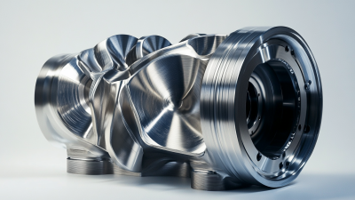
John T. Parsons, recognized as a pioneer of numerical control, said, “The machine tool industry is the basic industry of the world.” His statement explains why Cnc Machining matters beyond the factory floor. A milled aluminum housing, for example, may require several tool changes, carefully measured offsets, and controlled spindle speeds. Small errors can leave visible tool marks or produce a part that fails inspection. Precision is practical, not decorative.

This article explains what Cnc Machining is and how it works. It follows the process from a CAD model to CAM toolpaths, machine setup, material removal, and final inspection. Readers will also see how axes, feeds, speeds, tolerances, and cutting tools affect results. The process often appears automatic. It is not effortless. Poor fixturing, incorrect measurements, or an untested program can still ruin expensive material. That weakness deserves attention.

The discussion combines manufacturing principles with workshop realities. It also considers accuracy, efficiency, safety, and repeatability. Some explanations may simplify advanced production methods. That limitation is worth remembering. Real machining decisions depend on the material, machine condition, tooling, operator experience, and required tolerance.
What Is CNC Machining and How Does It Work?

What CNC Machining Means and the Principles Behind It

CNC machining means controlling cutting tools with programmed digital instructions. CNC stands for computer numerical control. A designer first creates a 3D model in CAD software. CAM software then converts that model into toolpaths, speeds, feeds, and machining commands. The controller reads these commands and directs motors along the X, Y, and Z axes.

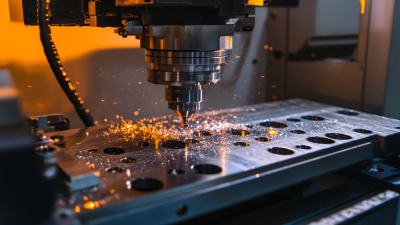
The basic principle is controlled material removal. A spindle rotates a cutting tool, while the workpiece stays fixed or moves on another axis. Encoders measure position and help the controller correct movement. ISO 6983 describes the familiar G-code system used by many CNC machines. However, G-code alone does not guarantee accuracy. Tool wear, thermal expansion, vibration, and incorrect workholding can change the result.

A practical example A practical example is a steel plate with four holes. The machine probes the surface, sets its coordinate origin, drills each hole, and checks the programmed depth. Small errors matter. A few hundredths of a millimeter can affect assembly.

Automation also explains CNC’s importance. The International Federation of Robotics reported 4.28 million industrial robots operating worldwide in 2023. CNC machines often work within these automated production cells. Yet automation is not magic. A perfect toolpath can still produce a poor part when the material, fixture, or cutting tool is misunderstood. Shop-floor judgment remains necessary, and that judgment is sometimes treated as less important than software.

Main Components of a CNC Machining System

A CNC machining system is a coordinated group of hardware and software. Its controller reads coded instructions and converts them into electrical signals. These signals command servo motors on the X, Y, and Z axes. The motors move the cutting tool or workpiece with measured precision. A spindle supplies rotational speed and torque. Tool holders, cutting tools, fixtures, and coolant complete the cutting zone.

Feedback devices matter greatly. Encoders report axis position back to the controller, helping correct movement errors. The machine frame must also resist vibration. Even a small deflection can leave visible marks on an aluminum surface. CAD software defines the part, while CAM software creates toolpaths and cutting parameters. Post-processing then converts those paths into machine-readable code. Communication hardware transfers the program safely to the controller.

The process begins with setup, not button pressing. An operator checks tool length, work offsets, clamping pressure, and the first toolpath. A dry run can reveal a dangerous coordinate mistake before cutting starts. It is not perfect, though. Heat, tool wear, and measurement uncertainty still affect results. A 2024 report by the International Federation of Robotics recorded 4.28 million industrial robots operating worldwide in 2023, reflecting wider demand for automated motion control. Market research from Fortune Business Insights valued the global CNC machine market at about 86 billion dollars in 2023 and projected continued growth through 2032. These figures suggest expansion, but they do not remove the need for skilled inspection and process judgment.

How a Digital Design Becomes a Machined Part

A CNC-machined part begins as a digital design, usually a CAD model containing dimensions, holes, radii, and tolerance notes. The model moves into CAM software, where an engineer selects tools, cutting speeds, feeds, and machining paths. The software then converts those decisions into machine-readable code. This stage is not automatic magic. A sharp internal corner may look acceptable on screen but remain impossible for a round cutting tool to produce.

The machine operator loads the material, secures it in a vise or fixture, and sets the work coordinate system. Probes may check the stock position before cutting starts. The spindle removes material in controlled passes, often leaving a small amount for finishing. According to the 2024 World Robotics report, more than 541,000 industrial robots were installed worldwide in 2023. That figure reflects manufacturing’s growing dependence on repeatable digital control, although CNC machining still relies heavily on human judgment.

After machining, inspectors measure critical features with calipers, micrometers, gauges, or coordinate-measuring equipment. They compare the physical part with the original drawing, not merely the 3D shape. Heat, tool wear, vibration, and poor chip evacuation can change the result. A simulation can miss these shop-floor conditions. That is why experienced teams adjust toolpaths, offsets, and inspection plans during production. Sometimes the first part is technically correct but still needs a better process.

Common CNC Machining Processes and Machine Types

CNC machining removes material from a solid workpiece through computer-controlled movement. A digital design guides cutting tools along programmed paths. The operator still checks tool offsets, workholding, speeds, and coolant flow. Small errors can create visible steps, poor surface finish, or incorrect dimensions.

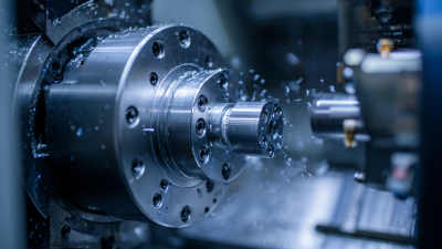
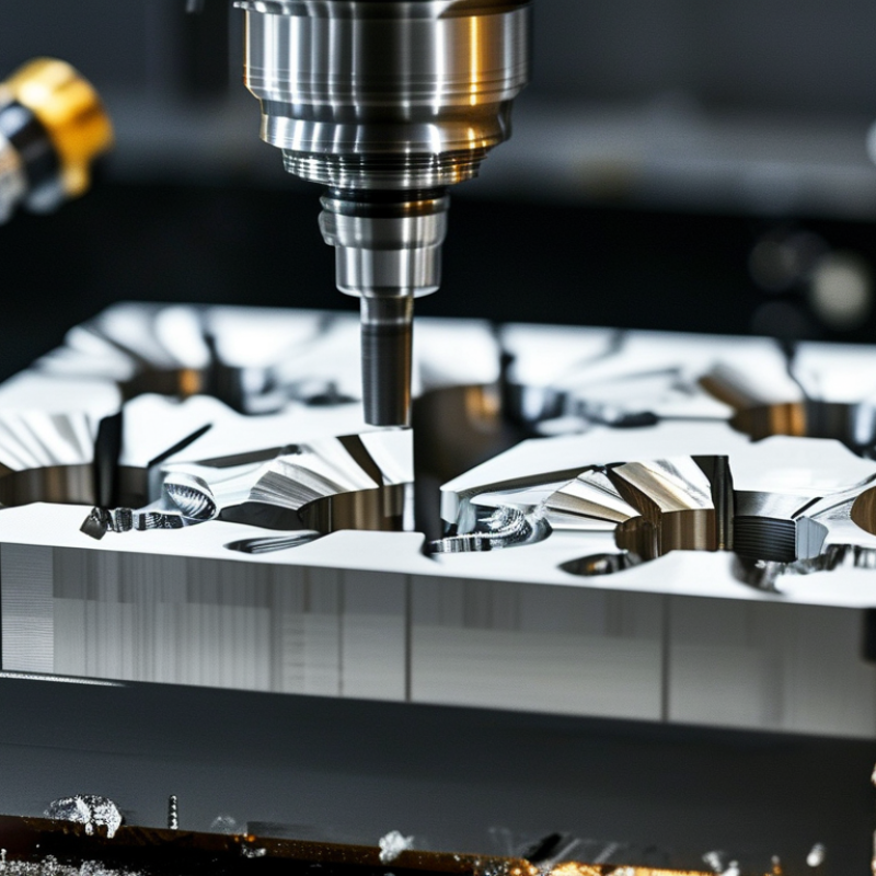
Milling is one of the most common CNC processes. A rotating cutter removes material from blocks of metal, plastic, or composite. Three-axis mills handle flat faces, pockets, and drilled holes. Five-axis machines reach angled surfaces with fewer setups. Turning uses a rotating workpiece and a fixed cutting tool. CNC lathes produce shafts, threads, bores, and tapered features. Mill-turn centers combine both actions for complex parts. Drilling, tapping, and reaming often complete the same setup.

Electrical discharge machining removes conductive material with controlled electrical sparks. It suits hardened metals and narrow internal shapes, although it can be slower. CNC routers commonly process wood, plastics, and sheet materials, while machining centers support heavier metal cutting. Choosing a machine depends on geometry, tolerance, material, quantity, and production speed. No process is universally best. In practice, fixture design can matter as much as machine power. A rigid fixture reduces vibration, but it may block tool access. Engineers sometimes select an impressive machine and overlook that limitation. A test cut, measurement report, and careful tool inspection reveal problems before full production.

What Is CNC Machining and How Does It Work? — Common CNC Machining Processes and Machine Types

Process or Machine Type How It Works Typical Cutting Tools Suitable Materials Common Applications Typical Strengths Important Limitations
CNC Milling A rotating cutting tool removes material from a stationary or moving workpiece according to programmed toolpaths. End mills, face mills, ball-nose mills, drills, and reamers Aluminum, steel, stainless steel, brass, titanium, engineering plastics, and wood Machine housings, brackets, fixtures, molds, pockets, slots, and complex 3D surfaces Versatile process with good dimensional control and the ability to create complex geometries Deep internal features may require special tools, multiple setups, or longer cutting tools
CNC Turning The workpiece rotates in a chuck while a stationary or driven tool removes material from its outside or inside diameter. Turning inserts, boring bars, grooving tools, threading tools, and drills Aluminum, steel, stainless steel, brass, copper, titanium, and plastics Shafts, pins, bushings, spacers, threaded parts, and cylindrical components Efficient for round parts and capable of producing accurate diameters and threads Less suitable for large flat surfaces or highly irregular, non-rotational shapes
CNC Drilling A programmed spindle feeds a drill axially into the workpiece to create holes at specified positions and depths. Twist drills, center drills, step drills, countersinks, and reamers Most machinable metals, plastics, composites, and wood Fastener holes, dowel holes, oil passages, ventilation holes, and mounting patterns Fast and economical for producing repeated holes with consistent locations Hole quality can be affected by chip evacuation, tool wear, material hardness, and workpiece thickness
CNC Grinding An abrasive wheel removes very small amounts of material to improve surface finish and dimensional accuracy. Aluminum-oxide, silicon-carbide, or diamond abrasive wheels Hardened steel, tool steel, ceramics, carbide, glass, and selected alloys Precision shafts, flat surfaces, bearing seats, dies, tools, and hardened components Excellent surface finishes and close dimensional control after rough machining Usually slower than milling or turning and generally used for finishing rather than heavy material removal
CNC Routing A high-speed rotating cutter moves across a sheet or panel to cut profiles, pockets, lettering, or contours. Single-flute, compression, straight, and carbide-tipped router bits Wood, plywood, MDF, acrylic, foam, plastics, and some aluminum sheets Panels, signs, cabinetry parts, prototypes, decorative profiles, and sheet components Large work areas and efficient cutting of sheet or plate materials Typically less rigid than heavy-duty machining centers and less suitable for very hard metals
CNC Wire EDM A thin electrically conductive wire removes material through controlled electrical discharges while the workpiece is submerged in dielectric fluid. Brass or coated conductive wire; no conventional cutting edge is used Hardened steel, tool steel, carbide, nickel alloys, and other electrically conductive materials Dies, punches, narrow slots, intricate profiles, and components requiring minimal cutting force Cuts hardened materials and produces detailed profiles with very low mechanical stress Limited to electrically conductive materials and generally slower than conventional cutting processes
CNC Plasma Cutting A high-temperature plasma arc melts conductive metal, while a gas jet removes the molten material along a programmed path. Plasma torch with replaceable electrode and nozzle Mild steel, stainless steel, aluminum, and other electrically conductive sheet or plate metals Metal fabrication, structural parts, brackets, plates, and rough-cut profiles Fast cutting of relatively thick conductive metal with automated shape control Produces a heat-affected zone and generally provides less edge precision than milling or wire EDM
3-Axis Machining Center The cutting tool moves along three linear axes, usually X, Y, and Z, while the workpiece remains fixed during a setup. End mills, drills, face mills, ball-nose cutters, and reamers Aluminum, steel, stainless steel, brass, titanium, plastics, and composites Prismatic parts, plates, pockets, slots, and relatively accessible surfaces Straightforward programming, broad availability, and cost-effective production Multiple setups may be needed to machine several sides or undercut features
4-Axis Machining Center Three linear axes are combined with one rotary axis, allowing the workpiece or fixture to rotate during machining. Standard milling cutters plus rotary-axis fixtures and specialized workholding Most materials suitable for CNC milling, including metals and engineering plastics Parts with features distributed around a side, indexed holes, and components requiring fewer setups Improves access to multiple faces and can reduce repositioning time Not all simultaneous multi-sided or undercut geometries can be completed in one operation
5-Axis Machining Center Three linear axes and two rotary axes coordinate tool and workpiece movement to reach multiple surfaces in one setup. Ball-nose mills, tapered mills, end mills, and specialty form tools Aluminum, steel, titanium, nickel alloys, composites, and plastics Aerospace components, medical parts, impellers, molds, turbine features, and complex curved surfaces Fewer setups, improved access to complex geometry, and shorter tools for certain surfaces Higher equipment, programming, fixturing, and inspection requirements
CNC Mill-Turn Center Combines rotating-workpiece turning with powered milling, drilling, and sometimes secondary spindle operations in one machine. Turning inserts, live milling tools, drills, boring bars, and threading tools Aluminum, steel, stainless steel, brass, titanium, and engineering plastics Complex rotational parts with cross-holes, flats, slots, threads, and off-center features Reduces handling and improves alignment between turning and milling operations More complex programming and setup than a dedicated lathe or milling machine
CNC Swiss-Type Lathe The bar stock is supported close to the cutting tool and moves through a guide bushing while tools perform turning and other operations. Small turning inserts, drills, thread tools, cutoff tools, and live tooling Stainless steel, brass, titanium, aluminum, nickel alloys, and plastics Small-diameter pins, medical components, connectors, screws, and precision shafts Excellent support for long, slender parts and efficient high-volume production Less economical for large-diameter parts or low-volume jobs requiring extensive setup changes

Key Benefits, Limitations, and Practical Applications of CNC Machining

CNC machining uses computer instructions to control cutting tools, spindles, and workholding equipment. A CAD model becomes machine code, then the tool removes material from metal, plastic, or composites. The process can hold tight tolerances while producing identical parts, from small aerospace brackets to automotive housings. A 2024 Grand View Research report estimated the global CNC machine market at about USD 88 billion in 2023, reflecting strong industrial demand.

Its main benefits are repeatability, speed, and reduced manual handling. A programmed machine can cut the same hole pattern across hundreds of parts. It also supports complex shapes that would be difficult to produce by hand. Deloitte’s 2024 Smart Manufacturing and Operations Survey found that 86% of manufacturers viewed smart manufacturing as important for competitiveness. CNC equipment fits this shift through sensors, automated inspection, and production data. Small details matter. A clean toolpath can reduce vibration, scrap, and tool wear.

The limitations are practical. Machines require high upfront investment, trained programmers, and regular calibration. Fixturing errors can ruin an entire batch. Cutting tools also wear gradually, even when the program remains unchanged. CNC machining may waste more material than additive processes, especially when a large billet becomes a thin component. It is not always economical for one simple part. The best applications involve repeatable production, close tolerances, and durable materials. Still, operators must question automated results. A perfect simulation cannot detect every loose clamp, warped blank, or unexpected burr.

Certified Quality System

© North Easton Machine Company, Inc. All rights reserved. • Site: Blog
NORTH EASTON MACHINE • 218 Elm Street • North Easton, MA 02356 • 508-238-6219